Making the Joints.
I imported the leg geometry into Maya and began by creating a new layer for the model. I named this 'leg_geo'.
I then put the model into 'Side view' to look at the left side of the leg. I clicked on the 'Skeleton' tab and selected the 'Joint tool' from the drop down list.
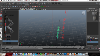
Using the Joint Tool, I began creating the skeleton for the leg geometry by estimating where the joints would be in correspondence to the leg model. Starting with the hip joint to the knee and so on.
I carried on making the joints for the ankle, ball of the foot and the toe. When creating the joint between the ball and the toe, I held down the 'shift' button to create a straight connection between the two.
Once I completed making the joints/skeleton I pressed enter and went back into perspective view. As you can see, the skeleton of the leg has been positioned at '0' on the X axis, which is not aligned to the left leg at all.
I simply selected the leg skeleton and used the 'move' tool to align it with the left leg geometry.
I needed to make sure that my 'knee' joint's Y axis points into the direction of -Y so that the rig would move correctly later one. To do this, I pressed fn (function) 8 on my keyboard and pressed the '?' symbol in the tool bar. This showed each joint's axis angles. As you can see, the knee joint's Y axis is not pointing in -Y.
I selected the knee joint and selected the 'Orient' tool settings from the Skeleton tab in the menu bar.
The settings menu showed to me the direction in which the Y axis was pointing to. At the time it was +Z so I changed this to -Y
This fixed the Y axis into the correct orientation.
To make it easier and efficient, I needed to label all the different parts of the rig. I went to the 'Panels' tab and selected 'Persp/Outliner'.
This showed all the joints I had made. I changed all the names of the joints to match the different parts of the leg, labeling the left leg in specific with _L after the joint name.
In the settings I selected to mirror the skeleton to the YZ axis, so the new leg copy would appear exactly in the right leg geometry.
Here are both legs mirrored and labeled efficiently with their own layers.
I now needed to make a center of gravity point between both of the legs. This COG (center of gravity) would take control over both legs as their parent. I began making this joint by going into 'Front view' so I could evenly place it between both legs.
I then held shift and click directly above the joint. This new joint will be the 'spine' to the leg rig.These two points will be the main controllers to the legs.
To parent the new joints to the legs. I firstly selected one leg, then the COG and pressed 'P' to create a parental bond. This made the COG the parent and the leg the child. I repeated this process for the other leg also.
Making the IK Handles and Weight.
For this part of the leg, I had to create an IK handle between the hip and the ankle. In the settings I HAD to set the type of IK handle to an 'RP Solver'.
Here is the first IK handle between the hip and the ankle. This will create movement between them with the inclusion of any other joints, such as the knees will play the most effective role in this connection.
I repeated this process to the right leg.
Now that both legs had the RP IK handles set, It was then time to bind the leg geometry to the skeleton. To do this I selected the skeleton and the leg geometry, went into the 'Skin' tab in the menu and selected 'Bind Skin/smooth bind' settings.
In the settings menu, I had to change a few settings so that the skin would bind correctly to my rig. I changed the skinning method to 'Dual Quaternion' and the maximum influences settings to '3'
To check the skin had bound correctly, I moved the ankle with the leg geometry visible. This image shows the rig and leg geometry skin bound correctly.
After making both RP solvers between the hip and ankle, it was time to add the other IK handles to the rest of the foot. For the ankle, ball and toe, I had to to use a SC solver instead. I repeated these steps across to the other leg, so that both legs had the same IK handles. The reason I had to use two different types of IK handles was because the RP requests only the location information from the IK handle when calculating solver movement, whereas the SC requests both location and orientation.
Now that both the legs had all their IK handles set and the skin had been successfully bound, it was now time to play with the weight paint tool.
The weight painting tool enables me to look at the difference joints of my leg and see how the weight is distributed in motion. I bent the left leg to see what the weight was doing to the hip and knee part of the geometry. In the paint settings to the left of the image I could freely cycle through each joint of the leg in case any part needed altering. Using the weight painter gives the legs a realistic look when the the joints move. Muscle and mass will bend and stretch accordingly to replicate the physics of a real leg. In this particular area highlighted in white, I can see that where the knee bends, a lot of the weight is uneven and 'skinny' looking behind the calf. To change this I had to add more 'white' to give the calf more weight. An area that has more white will be weighted more than an area in black.
On the 'joint operation' section of the settings i changed the mode to 'add' instead of replace, this would add the weight on. I would also use the 'smooth' mode when softening the harshness of some weights.
I began adding weight behind the calf and around the front of the knee. This made the calf look more weight and realistic than previous, as when the leg bends, the calf would not squish and stretch into the knee as much.
I then focussed on the thigh section as at the top of the hip, the skin was skinny and a bit disfigured.
I add the weight to the groin and top part of the thigh to give the model more definitive muscle in this position. When the leg lifts in this way, the top part of the thigh gains more weight as it squashes, so I had to add weigh here to represent this.
Reverse Foot Lock.
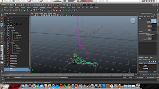
To have full control of the leg, including the positions of the joints in the foot, It was crucial to make a reverse foot lock control that would enable this to happen. I began by putting my left leg skeleton into side view so I could see the entire foot. I then click on the 'Joint' tool to begin create the joints for the reverse foot lock. However, for this to work I had to make the joints in reverse order. I started with the controller directly below the ankle joint.I then connected that joint to the toe, ball and finally the ankle.
I pressed enter and my reverse foot lock joints had been made.
I went back into perspective mode and noticed that my foot lock was not aligned with the original leg skeleton. I needed the reverse foot lock to be exactly where the other foot is, so I could make it act as a controller.
I simply used the move tool and dragged into place with the original left leg skeleton.
For the reverse foot lock to work, I needed to pair each joint with the IK handles on the skeleton. This will enable full control of the foot to be used at a single point. To do this, I selected the first reverse joint, which in this case was the ankle.
I then selected the IKHandle from the ankle joint on the original skeleton
From there, I went into the 'Skeleton' drop down menu and selected the 'Parent' tool. This then connected that joint to the IK handle, meaning when I move my reverse foot lock in the future, it will control the movements of the ankle.
I repeated this process backwards from the ankle, ball to toe.
After all the joints and IK handles were parented, I moved the controller underneath the ankle to check that the reverse foot lock acted as it should. In this image you can see how the foot lock controls the left foot's skeleton.
Now to make the reverse foot lock more efficient, I had to add a controller to it. I went into the 'Create' tab in the menu, 'NURB Primitives' and selected the 'Circle' shape. A Nurb is used as a controlling point within animations or rigs.
Once the Nurb circle has been created, I held down the 'V' key on my keyboard and snapped it to the first joint of the reverse foot lock. This was where I wanted my controller to be.
I then went back into 'Create' and selected the 'Freeze Transformations' tool. This makes the axis of the controller revert to the point of '0'.
I selected the reverse joint and the Nurb circle controller.
Then went into the Skeleton menu and clicked on the 'Point' tab. This then made the Nurb the controller of the reverse foot lock functions.
Here is the new Nurb controller in action.
I repeated the reverse foot lock and Nurb process to the right leg.
Here are both legs with their reverse foot locks and Nurb controllers. In the perspective outliner and layers section you can see I have clearly labelled each joint and handle. This is a much easier and efficient way to cycle through the different components.
In this image you can see how the reverse foot lock works with the entire legs model. The foot moves in correspondence to the way the leg is bending.
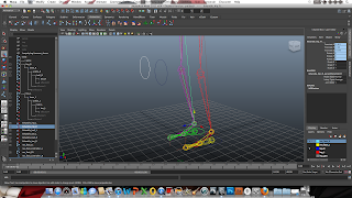
Now, I needed to repeat a similar process with the Nurb controllers and create two 'Pole Vectors' for the RP IK handle. This will give me control over the direction the leg will turn from the hip to the ankle. To do this, I made another two Nurb circles directly in front of both knees.
I started by selecting the right Nurb circle and the right leg's RP solver at the ankle.
I then went into the Skeleton menu and selected the 'Pole Vector' tab.
Here you can see the pole vector connecting to both the Nurb controller and the RP IK handle. This now means that the Nurb circle will control the movements of that solver.
I repeated this process onto the left leg also.
To show how the new Pole vector works, this image above shows that when the Nurb is moved the leg moves in relation to it.
Here is my fully rigged and finished set of legs. In this image I am demonstrating both the uses of the Pole Vector and the Reverse foot lock controller.


No comments:
Post a Comment